|
Fog ExampleIn this example, we show how to make use of fog in the scene graph. Fog is an effect to get depth-cueing for relatively cheap cost and makes for some nice visuals when used properly. In Aviatrix3D, there are a couple of different ways of using fog in the scene graph to get various effects. This example will show each of the different ways of doing that.
Understanding the basics of Aviatrix3D FogIn OpenGL fog forms part of the lighting equations. As part of the final pixel colour, a computation is performed that works out the depth of the fragment and then applies a fractional amount of the desired fog colour to the object. Turning this around and looking from the other direction - fog only is applied to items that make it through the rendering pipeline. If there is nothing to render, then fog is not applied. If you have objects in the scene, and no background geometry, then you won't see any fog colour. This is the first limitation of the OpenGL model, before you even get to the Aviatrix3D interpretation over the top of that. If you would like to have your fogged objects blend into the background, then you must set the background colour to match the fog colour.
To Aviatrix3D, fog is a node in the scene graph - specifically a Leaf node like
Local fog effects are useful, but many applications require something far
simpler - they just want to have a global distance-based effect. If this is
more your requirements, we cater for that too. As part of the
Setting up the applicationFor the first three examples we are going to use the same application framework and just vary the details. Because fog is something that is applied on the basis of the object's distance from the camera, these demos make use of animation so that you can see how the fog changes with depth. To do this, we create a number of primitives with a single colour and have them animate around a circular path - or, more correctly, have a single parentTransformGroup that we change the rotation matrix on and have all
the children underneath that.
The first part of the demo application is the observer needed to animate the
primitives. This is a standard
public class FogObjectAnimation
    implements ApplicationUpdateObserver, NodeUpdateListener
{
    private Matrix4f matrix;
    private TransformGroup transform;
    private float angle;

    public FogObjectAnimation(TransformGroup tx)
    {
        matrix = new Matrix4f();
        matrix.setIdentity();
        transform = tx;
    }
As you can see, it takes an instance of the TransformGroup that
will be animated, and sets up a local matrix to use for doing that animation.
The per-frame tick just tells Aviatrix3D that you'd like to mess with that
same
    public void updateSceneGraph()
    {
        transform.boundsChanged(this);
    }
The rest of the work is done in the callback when the transform is ready to
update:
    public void updateNodeBoundsChanges(Object src)
    {
        angle += Math.PI / 500;
        matrix.rotY(angle);
        transform.setTransform(matrix);
    }
As you can see, nothing too unusual about the code here. The interesting parts
are in the main application.
In the main application, the basic framework is the same as the other examples
- pipeline, surface, Swing setup etc. Setting up the scene graph is almost
identical too. To aid in the visualisation of the fog, a convenience method is
created that will take our parent
    private void createPrimitives(int num, Group parent)
    {
        double angle_inc = 2 * Math.PI / num;
        double angle = 0;
        Vector3f translation = new Vector3f();

        Matrix4f matrix = new Matrix4f();
        matrix.setIdentity();

        Material material = new Material();
        material.setDiffuseColor(new float[] { 1, 0, 0 });
        material.setSpecularColor(new float[] { 0.4f, 0.4f, 0.4f });
        material.setLightingEnabled(true);

        Appearance app = new Appearance();
        app.setMaterial(material);

        for(int i = 0; i < num; i++)
        {
            float x = 0.5f * (float)Math.sin(angle);
            float y = 0.5f * (float)Math.cos(angle);

            angle += angle_inc;

            translation.x = x;
            translation.z = y;

            matrix.setTranslation(translation);

            TransformGroup tg = new TransformGroup();
            tg.setTransform(matrix);

            parent.addChild(tg);

            switch(i % 4)
            {
                case 0:
                    Box box = new Box(0.125f, 0.125f, 0.125f, app);
                    tg.addChild(box);
                    break;

                case 1:
                    Cone cone = new Cone(0.25f, 0.125f, app);
                    tg.addChild(cone);
                    break;

                case 2:
                    Cylinder cyl = new Cylinder(0.25f, 0.125f, app);
                    tg.addChild(cyl);
                    break;

                case 3:
                    Sphere sphere = new Sphere(0.125f, app);
                    tg.addChild(sphere);

            }
        }
Now, to place the primitives into the scene graph, you'll just replace the
normal geometry setup of the basic example with this snippet of code.
        Group scene_root = new Group();
        scene_root.addChild(tx);

        TransformGroup shape_transform = new TransformGroup();

        createPrimitives(4, shape_transform);

        scene_root.addChild(shape_transform);
And complete the base scene setup later in the method by registering our
animator:
        Scene scene = new Scene();
        scene.setRenderedGeometry(scene_root);
        scene.setActiveView(vp);
        scene.setActiveFog(fog);

        sceneManager.setScene(scene);

        FogObjectAnimation anim = new FogObjectAnimation(shape_transform);
        sceneManager.setApplicationObserver(anim);
That's it for the application framework that we'll use for these demos.
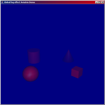
Global FogTo use a global fog, you will first need to create an instance of aFog node. When doing that there are a number of different
parameters to provide. The most useful one is the colour to make the fog.
Since we're also going to want to have the background blend with the fog,
a global constant has been declared with the desired colour:
private static final float[] FOG_COLOUR = { 0, 0, 0.5f };
Next, we want to have the background clear to that all the time, so tell the
surface about the colour it should clear to. This line of code should be
inserted into the standard setupAviatrix() method that is common
to these demo applications.
surface.setClearColor(FOG_COLOUR[0], FOG_COLOUR[1], FOG_COLOUR[2], 1);Next we need to create an instance of the Fog node and set it's
colour. This code will go into the setupSceneGraph() method,
before the creation of the Scene as above.
	Fog fog = new Fog(FOG_COLOUR);
	fog.setLinearDistance(0.1f, 3f);
	scene_root.addChild(fog);
As you can see, there is a call to setLinearDistance(). Fog has
have a number of different ways of calculating just how much to obscure the
object colour with fog colour. These equations determine the fall-off rate
between being visible and not visible. By default, the node uses the linear
equation. (This can be changed via the constructor or method calls). Linear
fog requires the setting of the distances where the fog starts to take effect
and where it is at full opacity (nothing is visible except the fog colour).
The default values are 0 and 0, so this method call is used to set some more
realistic values. In this case 1 and 3 are used because they represent roughly
the extents of the path that the primitives rotate through. The distance is
distance from the current camera location and is always relative to the camera.
If you're aiming to achieve objects fading out in certain parts of the world
more than others regardless of camera distance, then you'll need to make use
of the volumetric fog techniques discussed later.
To make the fog into a global fog, then you need to register it with the
	...
	scene.setActiveView(vp);
	scene.setActiveFog(fog);
That's all there is to it for global fog. If you run the BasicFogDemo you'll see the following on screen:
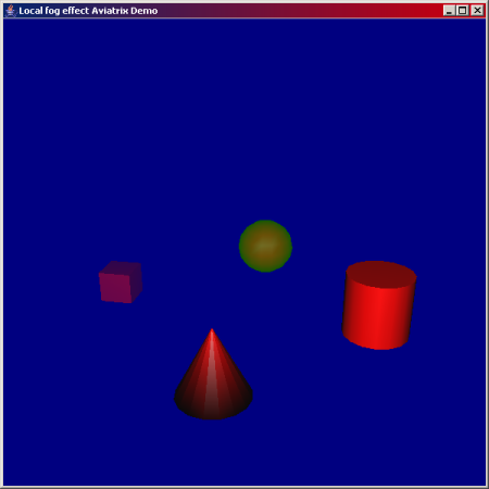
Local FogTo use local fog effects, the process is very similar. You'll still need to create aFog node and place it in the scene graph, just there
will be a slightly different setup. Since want the fog to be local, we don't
include the step to register it with the scene instance. That won't be enough,
we also need to instruct the fog that it is to be used for local effect too.
This is done by calling the setGlobalOnly() method with a value of
false. Alternatively, you can set the same flag in the
constructor. In this demo, that's what we do, and the code now looks like this:
	fog = new Fog(FOG_COLOUR3, false);
	fog.setLinearDistance(2, 3);
	tg.addChild(fog);
Once that is done, the node will use local fogging effects.
To make the demo more appealing and better illustrating the effects, we've
changed where that fog node instance is placed in the scene graph. This time,
the instance is registered in the same group as the primitive itself so that
you can see the individual fog effects. To accomplish that, we modify the
		switch(i % 4)
		{
			case 0:
				Fog fog = new Fog(FOG_COLOUR1, false);
				fog.setLinearDistance(1.5f, 3);
				tg.addChild(fog);

				Box box = new Box(0.125f, 0.125f, 0.125f, app);
				tg.addChild(box);
				break;

			case 1:
				Cone cone = new Cone(0.25f, 0.125f, app);
				tg.addChild(cone);
				break;

			case 2:
				Cylinder cyl = new Cylinder(0.25f, 0.125f, app);
				tg.addChild(cyl);
				break;

			case 3:
				fog = new Fog(FOG_COLOUR3, false);
				fog.setLinearDistance(2, 3);
				tg.addChild(fog);

				Sphere sphere = new Sphere(0.125f, app);
				tg.addChild(sphere);

		}
As you can see, the box and sphere will be effected by local fog, but the
cylinder and cone will not be. The visual effect is that you'll see the box
and sphere change to their fog colours as they rotate away from the camera, yet
the other two will not change colour even though they follow the same path. A
snapshot of this effect below shows heavy green tinge of the sphere and blue
tinge to the box, while the cone and cylinder remain bright red.
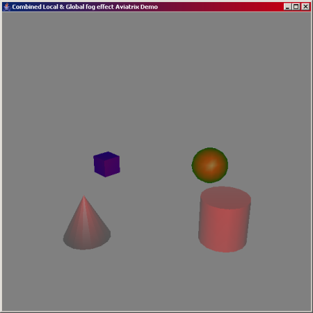
Combined Local and Global FogFor the third demo, we combine the code from the first two to illustrate how the fog scoping rules work with global and local versions. There's only a small change to the code from the previous examples. To make it clearer where the global effects are and where local ones take place, we've juggled the fog colour constants. The global fog is now grey and the two local versions remain blue and green.
The combined code is placed in the
Note: One bug that I encountered during this development was issues with
the ATI drivers. Prior to the 7 July 2004 version of the drivers, the fog
colour changes for each primitive would not take effect. If all you see are
grey primitives with no green or blue versions, update your drivers and it should
be fixed. It appears there were some bugs with the Volumetric FogVolumetric fog makes use of another capability of OpenGL - the ability to give every vertex a specific "depth" in the fog. In previous examples, the amount of fog to apply to a primitive was decided by the depth of that point in space from the camera location. This makes it impossible to do visual effects like a foggy valley in a mountain range. OpenGL introduced a concept called Fog Coordinates that allow you to override that default behaviour and tell the application exactly what numbers to use as the "depth" when interpolating the fog colour over the primitive.
Fog coordinates, because they are associated with individual vertices, are
specified as part of the Fog coordinates describe an artifical depth to the geometry to replace the automatically calculated one. This depth is any number that can be greater than or equal to zero (though negative values are allowed, just highly discouraged). As a depth, there is only a single value, so for each coordinate, you only need a single float which is the visual depth to use for applying the fog. These coordinates will then be passed to OpenGL when the geometry is rendered and you will see the fog appear according to the coordinate values. Illustrating fog coordinates with the previous fog demo applications won't be particularly interesting as you won't be able to tell much visually. However, I did find a cool OpenGL demo application on the internet and decided to make use of it for demonstrating fog coordinates and translated it into java plus Aviatrix3D code. The rest TBD. |
|
[ Home ]
[ License ]
[ javadoc ]
[ Online Examples ]
[ Download ]
[ j3d.org ] [ J3D FAQ ] [ Tutorials ] [ Books ] [ Contact Us ] Hosted by Yumetech, Inc Last Updated: $Date: 2004-10-29 20:54:11 $ |