
|
|
|
Cameras and Viewing© Justin Couch 1999
Earlier in the chapter, we took a quick look as
The combination of
PhysicalBodyThe first part of modelling your virtual body is representing how you are looking at the world. ThePhysicalBody class represents how your
head is located in the world. In the real world, you rarely walk around with
your head at ground level, and most people have two eyes set some distance
apart.
The following physical head related attributes are modelled by the physical body class:
PhysicalEnvironmentWhile the previous class models the basic characteristics of your body needed for rendering, thePhysicalEnvironment class models the computer
environment that your body sits in. We've mentioned input devices a few times
before, the physical environment is that class that is used to manage and
install the various devices available on your computer. Typically these
features won't be used in a PC based app as every machine is different.
However, if you are building a one off system such as a large virtual
environment or other exotic hardware then these capabilities are very useful.
Audio DevicesOf all the device types available, only the audio device will be the one that is installed most of the time. If you wish to have sound in your world, then an audio device must be installed. Another reason for installing an audio device is to choose between a number that may be available on your system: for example a standard FM OPL3 card and a 3D spatialization card.
You cannot write an audio device directly, Instead the drivers either come from
a manufacturer or they are provided as part of the JavaSound Java Media API
set. There are two separate classifications of audio devices: standard stereo
devices are represented by Input DeviceIf you have a specialised device, like the classical Mattel PowerGlove, you might want to create a new input device. TheInputDevice
interface is used to represent any sort of external input device in
combination with the Sensor class. Between these two, it is
possible to represent any arbitary input device - including multiple button
systems like the current crop of high range joysticks and throttle controls.
Moving Geometry with the ViewProbably the most important aspect of setting up camera objects is to be able to associate some geometry with the camera and have it move around with it. This Head-Up-Display forms part of the scene graph and can contain the normal 3D objects. The result is like a 3D dashboard with the geometry.
ViewPlatforms are just a leaf node as far as the scene graph is concerned.
They do not have any special properties that make them different from other
objects. The result of this is that they may be placed anywhere in the scene
graph. Any grouping node that you place them under will effect the position
and location of the camera that is represents. If the camera is located under
a
Say you want to build your standard Amusement Park camera model that is
located in a virtual rollercoaster. The rollercoaster has defined geometry
that always exists regardless of whether the view is on the ride or not. To
make the camera move with the rollercoaster. you simply make sure that the
The HUD principle employs the opposite approach - instead of moving your view wherever the geometry goes, you move the goemetry wherever your view goes. In practice though, there is very little difference in the way that the scene graphs are structured. Figure 10.1 illustrates the differences between the two approaches. As you can see, the only difference is in the relative position of the view platform in the scene graph to the root transform that is used to drive everything about. Where the difference comes about is how the transform is driven. In the first case, the camera object is moved by the geometry that it is associated with while the second moves the camera directly. Figure 10.1 The scene graph used for a rollercoaster ride (top) and for a Head Up Display (bottom). 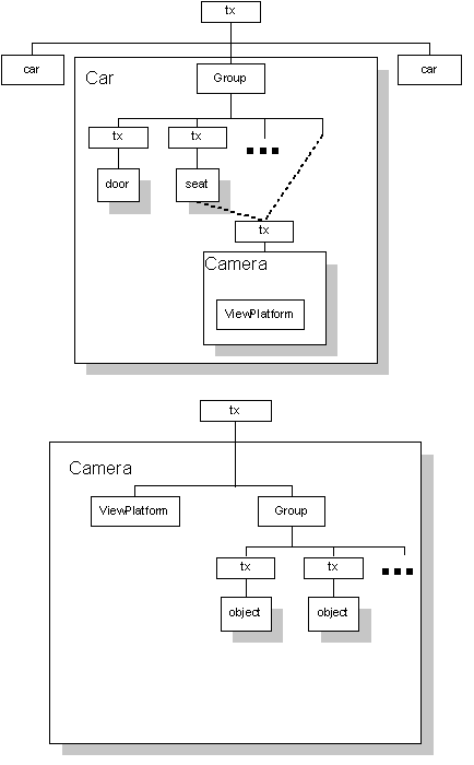
To create such a structure, we need to build almost exactly what you see in the image. Inside our camera model we need a group node that is the container for all the HUD objects:
private static final double BACK_CLIP_DISTANCE = 100.0;
private static final Color3f White = new Color3f(1, 1, 1);

private Group hud_group;
private TransformGroup root_tx_grp;
private Transform3D location;
private ViewPlatform platform;
private View view;
private DirectionalLight headlight;

private PhysicalBody body;
private PhysicalEnvironment env;

public Camera()
{
        hud_group = new Group();
        hud_group.setCapability(Group.ALLOW_CHILDREN_EXTEND);

        platform = new ViewPlatform();
With the basic top level structure complete and a default view platform
created, we may want some other options. We also want to create a root node to
hold everything. In this case, being a simple camera, a
TransformGroup is used as the root.
  location = new Transform3D();

  root_tx_grp = new TransformGroup();
  root_tx_grp.setCapability(TransformGroup.ALLOW_TRANSFORM_WRITE);
  root_tx_grp.setTransform(location);
  root_tx_grp.addChild(platform);
  root_tx_grp.addChild(hud_group);
A typical option for a camera is to include a headlight. This is a directional light that points exactly where the camera is pointing. Lights, like behaviours, always need a bounding area of influence. For cameras, we like to create a fixed length headlight because that makes it act like the miner type headlights when viewing the world.
private static final BoundingSphere LIGHT_BOUNDS;

static
{
        Point3d origin = new Point3d(0, 0, 0);
        LIGHT_BOUNDS =
                new BoundingSphere(origin, BACK_CLIP_DISTANCE);
}

  // create the basic headlight in the constructor code...
  headlight = new DirectionalLight();
  headlight.setCapability(Light.ALLOW_STATE_WRITE);
  headlight.setColor(White);
  headlight.setInfluencingBounds(LIGHT_BOUNDS);
  root_tx_grp.addChild(headlight);
To finish off the construction of the camera we need to create the
View object. The view needs both a PhysicalBody and
PhysicalEnvironment in order to run. A few other bits and pieces
are added to the View just to make sure that we can see
everything and then it is added to the root of the camera mini scene graph.
  body = new PhysicalBody();
  env = new PhysicalEnvironment();

  view = new View();
  view.setBackClipDistance(BACK_CLIP_DISTANCE);
  view.setPhysicalBody(body);
  view.setPhysicalEnvironment(env);
  view.attachViewPlatform(platform);

root_tx_grp.addChild(tx_grp);
}
That completes a basic camera object. To this, you will need to add methods that allow you to add and remove pieces of the HUD and to allow you to change the location and orientation of the camera. Code ImplementationWhile the model presented so far is pretty good representation of the real code that we would use, there are a couple of minor, but important items to add.If you took this class and just added it to your scene graph, you would see nothing other than a grey area on the screen. The reason for this is that we've forgotten an important part of the connection - all of the scene graph in the world is fine, but if our renderer doesn't know anything about it, we're stuffed.
If you recall some earlier discussions in this section, the connection between
the scene graph and the outside world is the
  public void setCanvas(Canvas3D canvas)
  {
    view.addCanvas3D(canvas);
  }
Now, to wrap up the rest of the example code from this chapter we need to
add the camera to the rest of the world. This is done through a simple
addition to the constructWorld() method of the main frame:
  private void constructWorld()
  {
    // create the basic universe
    universe = new UniverseManager();

    Camera cam = new Camera();
    Vector3f loc = new Vector3f(0, 0, 10.0f);
    cam.setLocation(loc);
    cam.setHeadLight(true);
    universe.addCamera(cam);

    cam.setCanvas(canvas);

    // add some geometry
    ExampleGeometry geom = new ExampleGeometry();

    universe.addWorldObject(geom);
    universe.makeLive();
  }
And that is it. You now just need to compile the code from the chapter and
run it on the command line. You should see a nice square object on a black
background appear before you now.
|
|
|